
Design of Steering System on Autonomous Car using Altair Simulation
In the final part in our four part series about designing a robotic car using Altair solutions, we look at the steering system and how that can be done.
This blog follows a series of previous blog posts covering the process of using the simulation suite of technology and software provided by Altair. In the prior posts, we have covered the process of designing the buck converter for the drive motors, creating a speed measurement system, and providing closed-loop feedback for the motor control system. Now that our driving subsystem is fully operational, we are ready to begin designing and implementing the steering subsystem. This part of the project will include data acquisition, goal finding, and steering input control.
Data Acquisition
First, we must have some way for the robot car to “learn about” or “see” its environment. In this example, we will use a small camera, seen below in Figure 1, mounted to the front of the car. Although the camera has a higher available resolution, we will adjust the settings so that it films in 640x640 pixels. This is just to simplify the data acquisition process and to ensure that the image data can be processed in a timely manner. This camera will be connected via USB to the microcontroller that controls the operation of the vehicle.
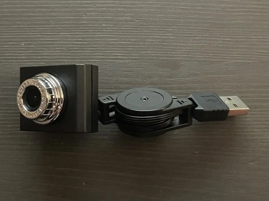
Fig 1. The camera that will be used to acquire image data for the robot car.
Now, what exactly will we do with this camera feed data? There are many options here, such as using artificial intelligence to identify specific objects or using fiducial markers to define a path. However, in this case, we will simply create a solid-colored line on the floor. This line will be physically created by sticking blue tape on the floor in the shape of a small driving circuit. We will orient the camera straight down at the front of the car so that it can view the blue tape at all times. This will serve as the goal for the car, as we will design a steering system to follow this line.
Goal Finding
Our robot car can now “see” the blue line, but we have not yet given it any instructions on how to analyze this line or what outputs we would like to generate. Again, there are many options here, but we will use the Computer Vision toolbox in Altair Twin Activate in conjunction with Altair Compose to handle this image data and to extract useful information. Altair Twin Activate is a powerful system-level simulation tool utilizing a user-friendly block diagram interface, and Altair Compose is an OML (Open Matrix Language) compiler, capable of a wide range of calculations and data manipulations. To begin, we will simulate this setup by providing an image of a blue line, formatted the same as the expected input for the car, as the start of our Altair Twin Activate model, which can be seen on the “Camera Input” display of Figure 2 below.
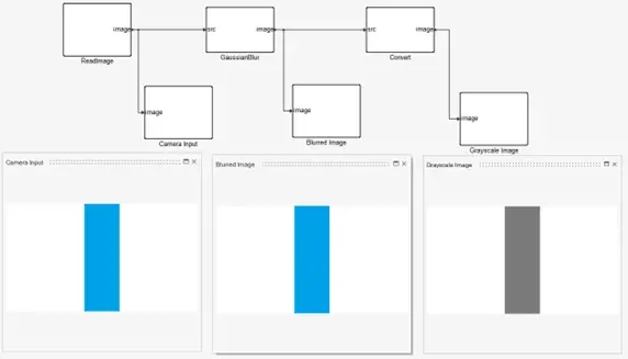
Fig 2. Initial image processing in Altair Twin Activate.
From there, we will continue to use the Computer Vision blocks to further process the image. We will apply a Gaussian blur to the image and convert it to grayscale, which can also be seen in the “Blurred Image” and “Grayscale Image” displays of Figure 2 above. These steps may seem trivial for this idealized simulation, but it will likely assist in cleaning up the real camera data once this is migrated to the actual vehicle. To finalize the process of collecting the camera feed as usable data, we will use the In Range block to set thresholds for our color ranges of the tape-line and extract only the location of the tape. Effectively, this will give us a binary matrix representing the original image, where any pixel occupied by the blue tape will equal 1 and all other pixels will equal 0. This is visualized by the complete example shown in Figure 3 below, where noisy input is simulated, and only the goal, the line of tape, is provided at the output.
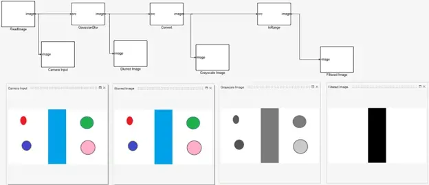
Fig 3. Example image processing to remove noise from image data in Altair Twin Activate.
The camera feed now exists as a matrix that we can begin manipulating. While Twin Activate has an impressive array of data handling blocks, we will streamline the process by implementing a custom OML block from Altair Compose. We can use it to write out a script that will determine the location and direction of the blue line ahead of the robot car. Figure 4 below shows this relatively simple script, and it does the following:
- Line 1 – Read current frame/image
- Line 2 – Determine the size of the image (we know it will be 640x640, but this is helpful if we wish to generalize this process in the future)
- Line 3 – Find the index of the middle row in the image
- Lines 4 & 5 – Extract the first (top) row and the middle row of binary pixel values from the image matrix
- Lines 7 & 8 – Find the indices of all nonzero entries on the first and middle rows of the image (nonzero values indicate the location of the blue tape)
- Lines 10 & 11 – Find the mean of the indices of the nonzero values; this gives us the average location of the blue tape at the top of the image (future direction of tape) and the average location of the blue tape in the middle of the image

Fig 4. Altair Compose script to locate blue line in image data.
Since we have the location of the blue tape at two heights in the image, we can figure out the direction the tape is heading, which will subsequently tell us which direction to turn:
- goal_top equals goal_mid – This indicates that the tape is straight forward, and no turning is necessary
- goal_top is less than goal_mid – This indicates that the tape is curving to the left, so a left turn is needed
- goal_top is greater than goal_mid – This indicates that the tape is curving to the right, so a right turn is needed
Once we are satisfied with the performance of this script in Altair Compose, we will use the OML Block operator to import our custom script into Twin Activate. After we define and name the input and output ports on this block, we can pass the filtered image to the script to extract the current direction of the blue line. Figure 5 below shows the example of the straight line, and, as expected, the goal_top equals goal_mid, meaning the simulation correctly “understands” that it is a straight line.
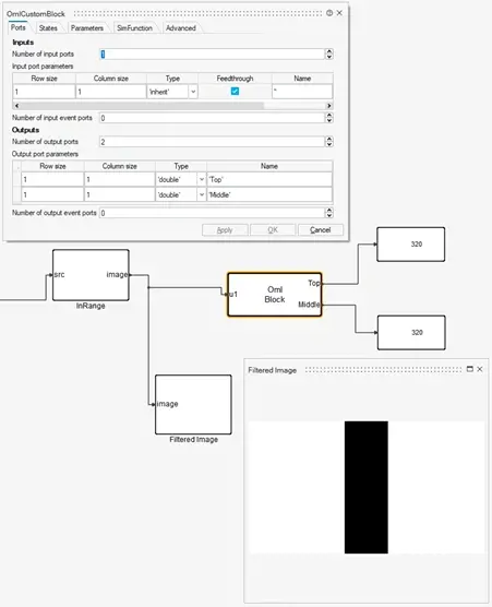
Fig 5. Integration of Compose script into Twin Activate.
Similarly, we can test this process with an input image of the track curving to the right. Figure 6 below demonstrates that our model was able to see that the track at the top of the image has a great index, meaning it is further to the right, than that of the middle of the image. This means that the model successfully identified the right turn.
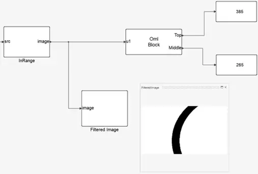
Fig 6. Example of integration with right turn.
Steering Control
We are now ready to take these measurements and use them to construct a steering control system. First, we will normalize the pixel indices to a decimal representation, where the 0-640 input is scaled down to 0-1. We will then find the difference between the normalized top position and middle position, which will yield a value between -1 and 1; a larger negative value indicates a larger left turn, a larger positive value indicates a right turn, and a value of 0 indicates a straight path. Figure 7 shows an example of this with the right turn from earlier. We can see that the output is 0.1875, which indicates a relatively small right turn, as anticipated.
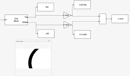
Fig 7. Normalization of model outputs.
We can now use the polarity and magnitude of this output from Twin Activate to act as inputs to the motor control for the servo motors that will steer the front tires left and right. If the number is positive (a right turn), we will turn Switches 1 and 4 to their ON state, allowing for positive voltage to turn the motors to the right, while a negative number (a left turn) will result in Switches 2 and 3 being ON, causing a negative voltage and a left turn on the steering motors. The magnitude of this number will tell us what magnitude of voltage to apply across the servo; for example, a positive 1 would mean we need to apply the max rated voltage (6 V) across the servo to turn as far to the right as possible. In the example highlighted previously, the number 0.1875 would correspond to +1.125 V across the servo motors. This can be accomplished with a buck converter designed in Altair PSIM, a versatile power electronics design and analysis software, which is shown below in Figure 8. If you would like to learn more about this side of the design process, be sure to check out the first blog in this series (Using Altair Solutions to Create a Robotic Car Part 1), where we walked through characterizing and controlling a DC motor.
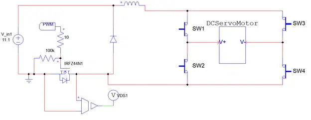
Fig 8. Altair PSIM bidirectional motor controller for servo motors.
Lastly, we will combine everything we have accomplished and load it onto our microcontroller. We will export the Twin Activate model as an FMU (functional mockup unit), and then we will import it into Altair Embed, a drag-and-drop embedded systems design software that has automatic code generation. We can also import the PSIM model directly into Embed to combine our direction-logic model, our steering motor control model, and our microcontroller all in one environment. As Figure 9 depicts below, we can piece these together and generate code that is compatible with our microcontroller to execute the process we have just designed.
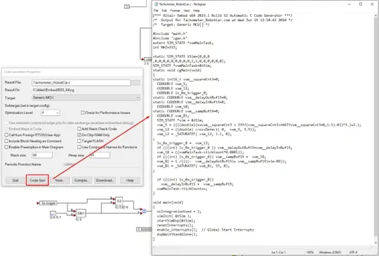
Fig 9. Use of Altair Embed to integrate simulations and generate code for microcontroller.
Results
Now we are ready to put the car to the test! Once we have finished constructing the robot, loaded all our code, and integrated the individual subsystems into one fully functional vehicle, we can see everything in action. Figure 10 below shows a brief demonstration of all systems working together to drive the car along the desired path at a desired speed!
_(1).gif)
Fig 10. Video of robot car autonomously following the blue line on the ground.
This concludes this series of blogs regarding the design and construction of an autonomous robot car using the power of Altair software. Throughout this project, we effectively used Altair PSIM, Embed, Twin Activate, and Compose to fully design and build this device. What else would you have added to this project? With Altair, the possibilities are endless, such as using Altair Flux to analyze the motors, or Altair FEKO to design some custom wireless communication with the car, or even maybe Altair AI Studio to build some form of artificial intelligence to instruct the car to follow specific objects, shapes, colors, etc. If you would like to see more content about this car, please be sure to check out our companion video series on our YouTube channel. As always, please reach out to us at TrueInsight.io if you would like to learn more about this project, these software solutions, or anything else Altair has to offer!