Behind the Scenes: Altair Inspire Cast Meshing with SimLab
Inspire Cast and SimLab work together to give users the best workflow in the industry. Look at Common errors, how to simplify your process.
When running a metal casting simulation using Altair Inspire Cast, the model needs to be broken up into simple pieces that make up a mesh. In the background, Altair SimLab creates this mesh and delivers it to Inspire Cast for you automatically. For most cases, this process works seamlessly. In this article, we will look at one of the few cases where we bump into a problem caused by some modeling practices that are not well-suited for simulation, and how easy it is to use SimLab to help track down the problem.
Casting simulation fails
Our casting CAD model includes a core and a riser.
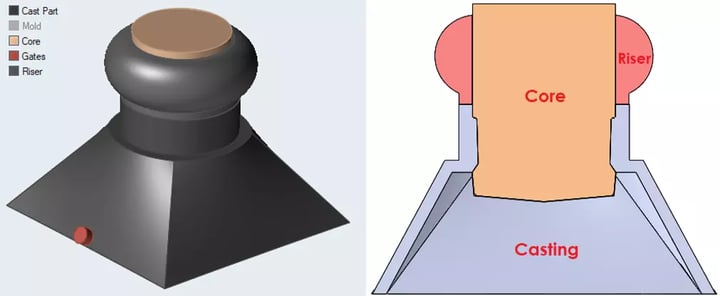
Figure 1 – Casting model with core and riser.
In this case, when we tried to run our casting simulation, we encountered an error.
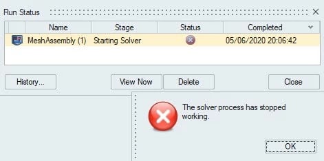
Figure 2 – Run our study and we got an error.
Although we may not be sure why we get this error, we should start by looking at the mesh, since this is what Inspire Cast uses for its calculations.
Open mesh file in SimLab
To look at our mesh, we will open the mesh in SimLab. The mesh file called “Mesh.slb” is found in the run folder.
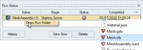
Figure 3 – Open the run folder to find our mesh file “Mesh.slb”.
After opening this file in SimLab and hiding the model body, we see some of the triangular mesh elements.
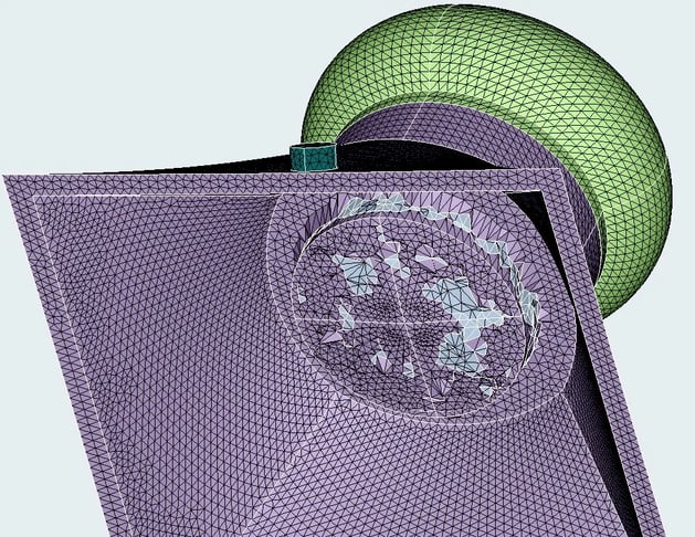
Figure 4 – What happened to the mesh down here? This looks like a mess.
There are some advanced meshing tools in Altair SimLab that also help you to track down problems like this if your model is more complex. The Quality tool allows us to filter elements that have bad quality.
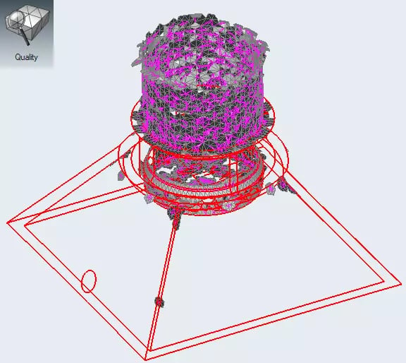
Figure 5- Finding bad quality elements using the Quality tool in SimLab.
Or we can section our mesh to try to get a full picture of these elements.
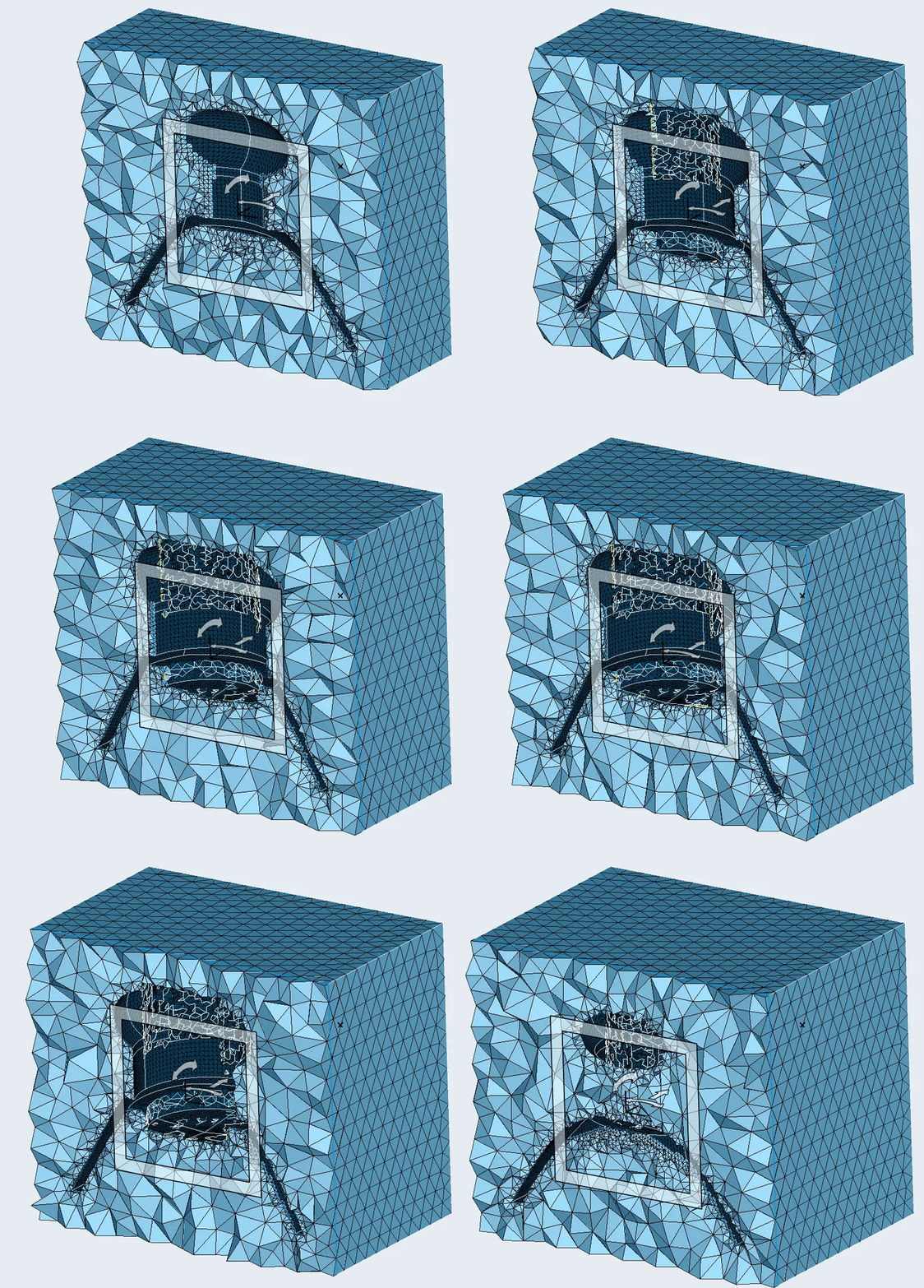
Figure 6 – Cutting plane in SimLab.
Now that we have identified the locations of the problems, we can take a closer look at the model to see how we can fix them.
Fix the problem using Inspire Cast direct editing
We can see that our CAD model had tiny gaps or walls that may have created some of the problems with the mesh.
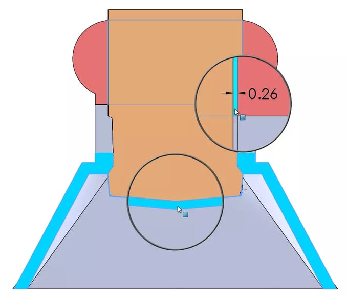
Figure 7 – Tiny gap between the riser and the core. Tiny casting wall between the core and mold.
Without having to go back to our CAD tool, we can use some of the features directly in Inspire Cast to fix this problem. We can drag-move faces and use the Cut tool.
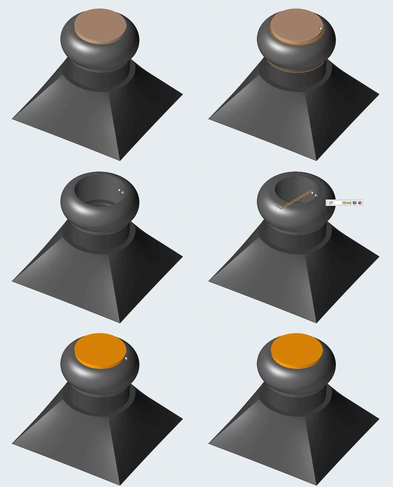
Figure 8 – Drag-move to close the gap. Inspire Cast uses smart priorities to resolve overlapping regions.
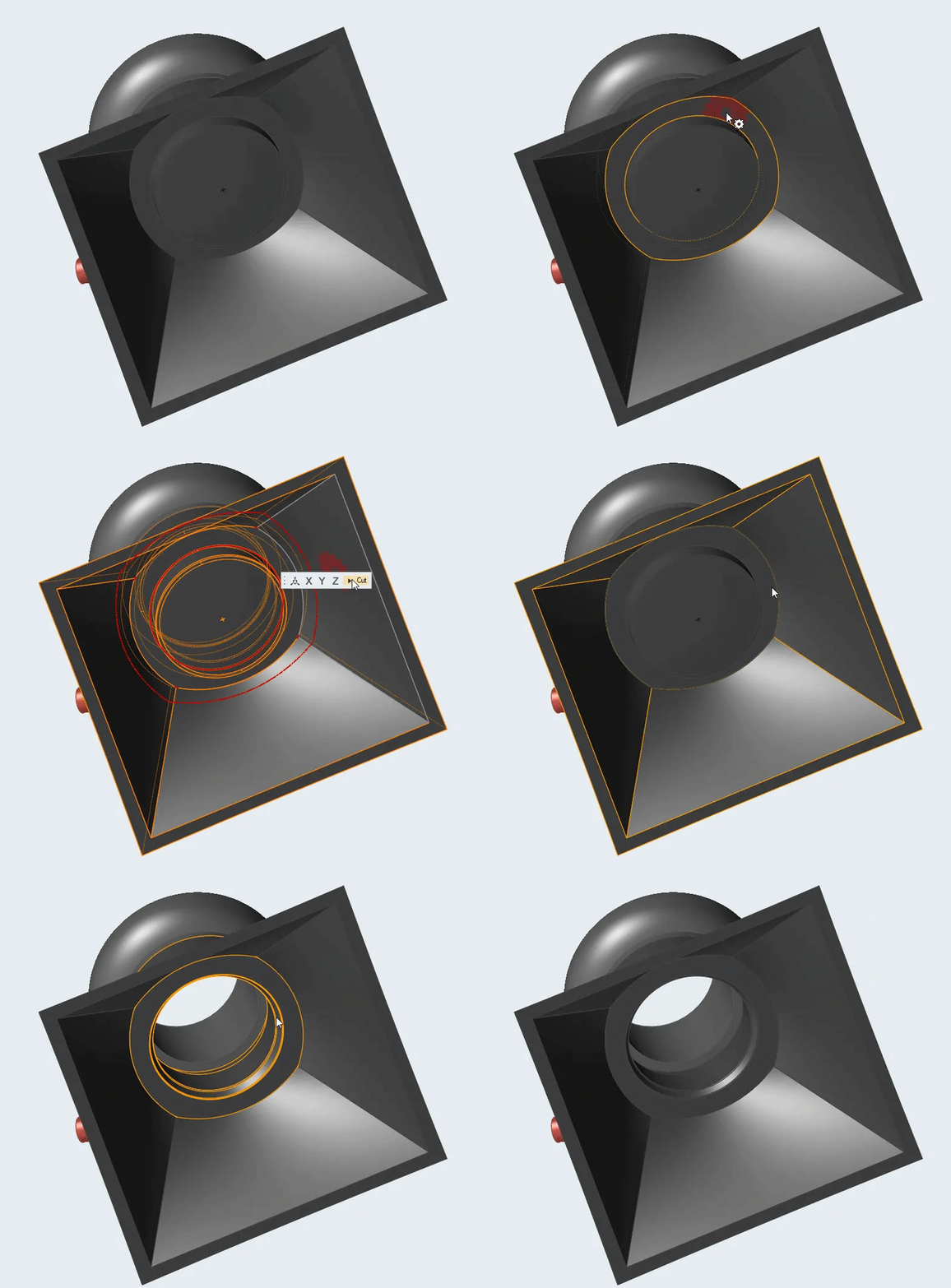
Figure 9 – Cut tool in Inspire Cast to trim off material.
After a couple more steps to clean up and combine the remaining bodies after the cut, we are ready to run our casting simulation.
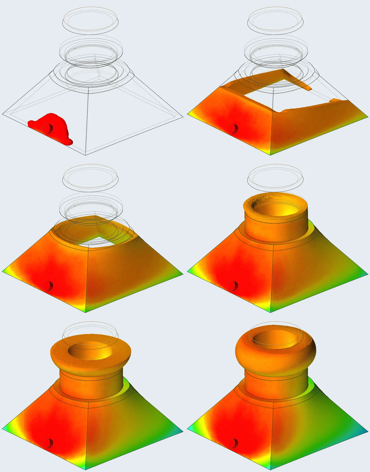
Figure 10 – Casting simulation completed!
Our initial study failed to run, but by opening the mesh file in Altair SimLab we were able to track down the source of the problem quickly. We then used some of Altair Inspire Cast’s direct editing tools to fix the problem and in minutes, we had a working model. The fact that we can leverage SimLab, a tool specially developed for quick and easy meshing for a wide variety of applications, alongside Inspire Cast, a tool built for metal casting simulations, makes this workflow possible.
If you would like more tips or some training when working in Altair’s Inspire Cast, contact us.
